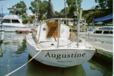
Photos of "Augustine"
..... Exterior
..... Motor Well
..... Lifelines
..... Jacklines
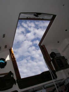
..... Interior
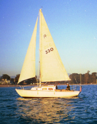
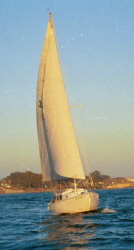
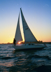
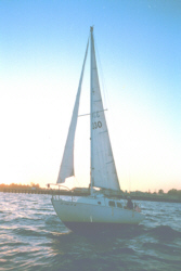
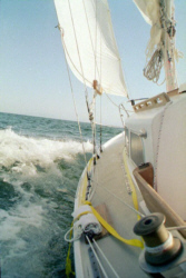
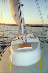
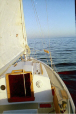
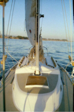
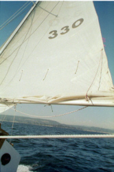
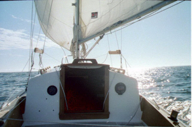
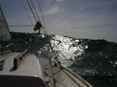
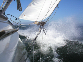
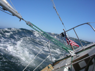
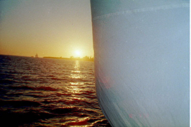
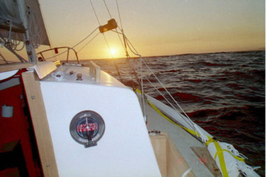
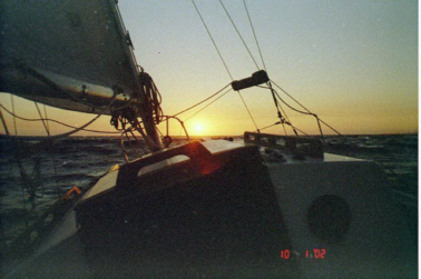
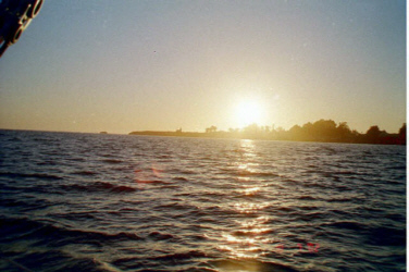
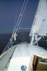
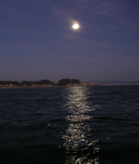
..... Under Sail
"Augustine" Structural Retrofit Page
"Augustine" Self Steering Page
"Augustine" Oar Page
"Augustine" Home Page
Photos of other Pearson Ariels
Drawings of The Pearson Ariel
"This Sailing Page"
e-mail to: myrmade@solopublications.com
This site has no affiliation with any manufacturer of sailboats. The contents provided in the reviews sections below or in letters to this page are the opinions of those who wrote them and not the opinions of the author of these pages.
The focal point of this site is the Pearson Ariel "Augustine," hull #330, the restoration of and modifications to Augustine, and some information on her sailing charactistics..
The other purpose of this page is to provide information on the Pearson Ariel, and to provide a portal for access to on-line information on the Pearson Ariel. Links are provided to other Pearson web sites.
Additional Information from printed brochures on the Pearson Ariel is provided on other pages linked to this site.
We will appreciate any corrections, additions or other suggestions for improving this web page.Photos of Pearson Ariels, information on Pearson boats, and links to other sites dealing with Pearson boats are welcome.
Photos of "Augustine"
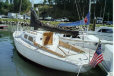
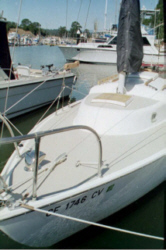
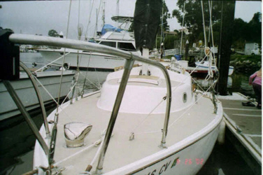
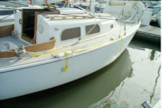
Exterior Photos

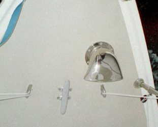

A four inch stainless steel cowl vent with screw-in stainless steel deck plate manufactured by Mariner Hardware was installed in the place of the original Mariniumm deck plate and cowl vent since the original was missing. This view also shows lifeline attachment in the bow area.
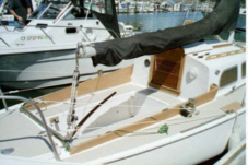
The cockpit table was made from a hardwood tray, 1 1/2 inch ABS pipe and fittings, and same dacron cord. The mounting bracket for the Garhauer lifting davit doubles as a mounting bracket for the cockpit table. It also serves as a convenient place to secure a mainsheet bag to keep the mainsheet from underfoot while under sail.
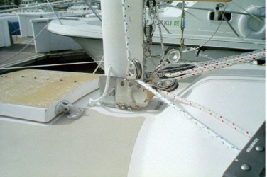
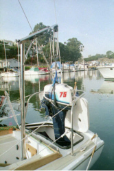
A dual action 8:1 / 4:1 Garhauer mainsheet block assembly was installed to facilitate the mast tabernacle operation. However, under most circumstances a less complicated 4:1 Garhauer mainsheet block assembly is used. The 4:1 block assembly, shown in the thrid photograph above, also functions in the tabernacle operation, but the level of effort is increased over the 8:1 block assembly. Far less mainsgeet line is used with this block.
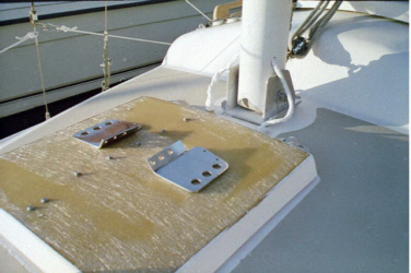
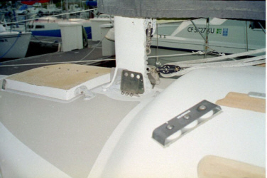
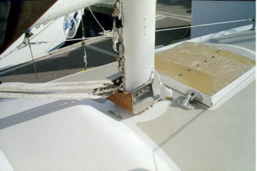
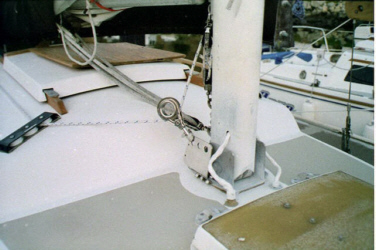
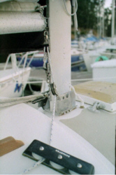
The mast base is set up for a mast tabernacle. In addition, two vertical stainless steel plates were designed to fit on the existing mast base plate to provide a place to attached the blocks to run the boom vang, halyards, reefing lines, etc back to the cockpit if desired. These custom plates were fabricated from ten (10) gauge polished 316 stainless steel manufactured by Aquarius Marine in Moss Landing, California.
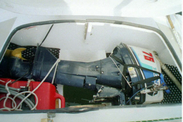
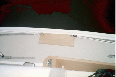
Lazarette Locker and Motor Well
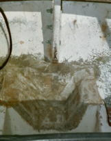
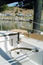
The photo above shows the backstay chain plate and the knee that supports it. Three bolts secure the chain plate to the knee.
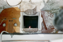
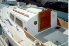
Modifications were made to the motor well by a previous owner. The photo above shows the motor well after modifications were but before it was painted. The well has been enlarged to accommodate a 7.9 hp four-stroke Honda outboard motor. Also shown is a custom gasoline tank platform designed and installed by a previous owner to accommodate a three-gallon plastic gasoline tank. The wood strip, which runs from the top toward the bottom of the photograph, fits into a groove on the bottom of the tank. The cleat shown in the photograph secures a line, which is run from the cleat to a bungee cord that extends over the tank to hold it securely in place.
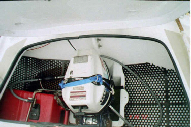
The photo above shows the Honda 7.9 four-stroke motor in place after replacement of the backstay chainplate and repainting of the lazarette locker.
The Honda 7.9 was replaced in 2003 with a Nissan 6 hp four-stroke motor. This motor weighs only sisty pounds. A three (3) gallon gas tank is currently used. This allows more rapid cycling of fuel under normal conditions. For extended trips a six gallon tank can be added to the lazarette locker.
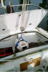

The credit for this adaptation goes to Gene Roberts, who discovered the relevance of the Garhauer Lifting Davit to the unique design of the Pearson Ariel's cockpit, counter stern, and outboard well, to Bill Phelon for including Gene's modified Garhauer Lifting Davit installation in the "Ariel Owner's Guide and Maintenance Manual," and to Myron Spaudling for his studied installation of Gene's lifting davit in the perfect location to lift the motor from the well and at the same time to transfer the majority of the stress to the aft port cockpit support post. This post, at least on Augustine, hull #330, appears to be well built, well bedded, and well supported on a wide base, which is glassed to the hull very near the turn of the bilge.
I followed Gene Robert's lucid cookbook for success in the Ariel Maintenance Manual to install the (modified as per Gene's specifications) Garhauer lifting davit on "Augustine". It took me two days, largely because this was my first installation of such a beast, and because I spent a lot of time measuring to ensure that my hull and cockpit configuration were the same as Gene's, and because I bedded the support hardware on the cockpit floor with Boatlife, Life Caulk, and wanted to let it set up for 24 hours before I cranked the bolts tight.
My measurements weren't precisely the same as Gene's, because placement of the center of the support post (stabilizer ball) 2.5 inches from the port cockpit wall necessitated a 7/8 inch thick extension support mounting block rather than one which was one inch thick. One the other hand, lumber yards refer to teak of 7/8 inches width as a "one by," so perhaps Gene really meant that the "extension support mounting block" should be a "one by" which would actually be 7/8 inches�. however, take Gene's advice and not mine in this regard. Had I used a one-inch wide mounting "extension support mounting block," the center of my stabilizer ball would have been 2 and 5/8 inches from the port cockpit locker.
Perhaps the dimensions varied slightly from year to year or from hull to hull. The Ariel cockpit floor is not a cored by a solid sheet like the deck, but instead is reinforced by one-by-three boards that appear to be fir like the cockpit support posts, but could be some other wood. The result is that the underside of the cockpit floor looks like a corrugated panel. The turn of the cockpit floor up to the wall is not cored. So when I centered the stabilizer ball 2.5 inches from the port cockpit wall, although all four holes were through a wood core, I would have been more comfortable one eighth of an inch further toward the centerline of the boat, because the backing plate partially overlaps the radius as the cockpit curves upward. Not to worry. It is still a stable and secure installation.
I also added teak compression plates to the underside of the cockpit between the stainless steel plate that comes with the davit mounting hardware, and the cockpit floor, and also to the inside of the port cockpit wall.
My only constructive criticism is that the Garhauer mounting hardware is designed so that the device can be mounted to a stanchion or other steel rail. This does not work on my boat due to the strength of the stern rails, and the relative weakness in the deck adjacent to the lazarette area, combined with geometric issues. In adapting the device to attach to a bulkhead (the cockpit wall), the heads of the mounting bolts face outboard and are thus on the inside of the cockpit locker rather than facing the cockpit. The mounting ring of the "extension support-mounting block" is welded to a steel plate. The steel plate, in turn, has two welded nuts to which the mounting bolts are attached. This is not a major issue, and the installation went very well, despite the rather odd situation of crawling inside of a cockpit locker to bolt through the glass to a nut on the outside.
The Garhauer lifting davit is a serious piece of stainless steel hardware available at very reasonable price. The Garhauer lifting davit is suitable to lift a motor with a 6:1 ratio from the well to be stored in the lazarette locker, cockpit locker, or drop that puppy into a dinghy or close to the dock with a certain amount of horizontal influence by the lifter or by another member of the crew. Using the davit, I generally swing the motor over the lifeline and lower it down on a commercial outboard motor cart, which I arrange with its handles on the aft deck and wheels on the dock.
The most recent Garhauer modification also makes it easier to lift a motor into a dinghy while operating the davit from the dinghy.
Don't forget to ask for Gene Robert's modification, which lengthens the support post, and if you don't already own one, buy a manual from the Association to tell you how to install your new davit in your Ariel.

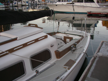

A lifeline system was installed where none had previously existed. No stanchions were used.The first goal of the project was to design and install a safe and secure lifeline system that could be made of either coated wire or Dacron line. Dacron 3 braided 1/4 inch line was used for this installation. The second goal was to provide a system that would be safe to use for support, and as an attachment point for a safety harness. The third goal was to accomplish goals 1 and 2 without installing stanchions or drilling additional holes through the deck.
A set of existing pad eyes at the bow just aft of the mooring cleat and a new through-deck eye bolt at the forward edge of the boarding step were used as the terminals for the forward portions of the lifeline system. A superfluous section of the Genoa Track was removed to permit the installation of a boarding step on each side. Two of the existing holes for mounting that section of track were utilized for the eye bolts. The two eye bolts are tied together below deck by a teak compression plate and a stainless steel backing plate. The forward lifeline system also utilizes the pin rail, which is secured to the lower shrouds, and also a shackle at the turnbuckle on the upper shroud, which functions as the pivot point for the mast tabernacle. The lower forward lifeline section between the aft terminal (forward boarding step eye bolt) and the pivot point shackle also functions as a bridle to stabilize the aft lower shroud during the tabernacle operation.
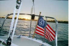
The terminals for the aft section of the lifeline system are the eye bolts at the aft edge of the boarding step and two points on the stern rail (push pit).
Turning blocks are used so that lifeline tension can be adjusted from the cockpit.
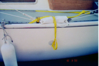
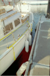
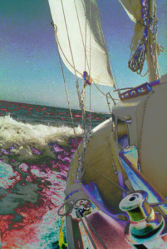
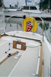
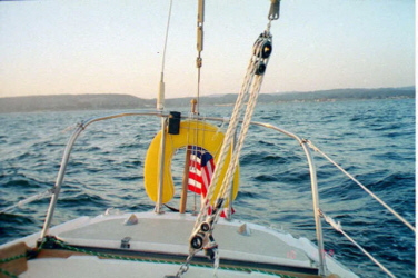
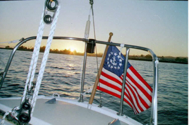
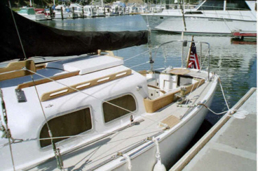
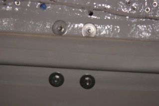
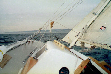
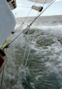
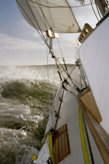
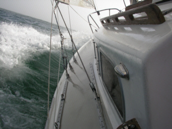
The photos above show the jackline system, which consists of one long sewn-in loop-ended length of nylon jackline webbing, a couple of bow shackles, and four Velcro straps. Each end of the jackline is fed through one of two through-deck bolted pad eyes at the bow and through another through-deck pad eye at the stern, to which it is shackled mid-length with a bowline and bow shackle. The trailing ends (tails) are then led forward outside of the lifelines and shrouds to the location of the base of the upper shroud, where the end loop hangs over the rail.
Velcro straps made by West Marine and intended for use as electrical cord straps hold the jackline tails to the base of the lifelines at the front end of the cockpit and to the base of the upper shroud. The jackline tail is also draped over the emergency boarding ladder (that rolled up white thing on the rail in the attached photograph). You can see the yellow jackline tail running across the rolled up boarding ladder. Thsi helps kep it from washing over the rail at forty (40) plus degrees of heel when the rail is down.
If you look closely, you can see the yellow Velcro strap just forward of the ladder that secures the aft end of the jackline tail. The rearmost through-deck pad eye, to which the aft end of the main part of the jackline is shackled is just forward of the winch in the foreground of the photograph.
The reason for taking the tail end of the jackline forward again and attaching it to the shrouds with a Velcro strap, is that if a person were to fall overboard forward of the shrouds, that person's harness tether would not be long enough for him or her to reach the boarding ladder. The two emergency ladders are attached on either side of the boat at the boardins step adjacent to the cockpit.If a crew member falls overboard forward of the shrouds, that person can clip onto the loop at the end of the jackline tail, and then unclip from the jackline itself, and then drift back on the tail to the emergency ladder located at the lowest point on the sheer line. Theoretically, the Velcro straps release as one drifts back. If the Velcro straps do not release for some reason, a yank on the jackline tail cases them to release.
I installed a second snap shackle on my stainless steel harness belt ring. That snap shackle can be clipped into the sewn-in end of the jackline that hangs over the gunnels at the location of the upper shroud. Once secured to this loop, the overboard sailor should be able to unclip from the three and six foot tether and drift back on the jackline tail to the emergency boarding ladder near the cockpit. This is primarily of importance when single handing.
The ladder location is the best place to board the boat from the water, since the hull is fairly vertical there, and there are good adjacent hand holds on deck. The emergency boarding ladderhas a yellow lanyard with a loop sewn into the end. That lanyard is suction-cupped to the outside of the hull, so that it won't blow back up onto the deck in the wind. As long as the suction cup is wet, it seems to stay fixed on the hull beneath the rub rail during a sail, even when the rail is buried.
When one pulls downward on the lanyard, the ladder unrolls. Standing on the bottom rung of the ladder will place a crew member at a level where the toe rail is at slightly above knee level and provide the crewmember with two handholds. There are three rungs on each ladder. The ladder rungs are made of pvc pipe with 1/4 inch Dacron line threaded through them. The ladder is attached to the through-deck bolted eye bolts at the forward and aft edges of the boarding steps by carabineers. The ladder is packed inside a perforated plastic sheet, which unrolls to protect the hull whenthe laddder is in use and serves to aid rolling and securement of the ladder.
The boarding ladder system needs refinement. The leeward ladder tends to wash overboard and unroll if the rail is buried. This neither damages the boat, nor the ladder, but it is a nuisance. I am currenly seeking a design of a revised retraint device for the stowed boarding ladders.
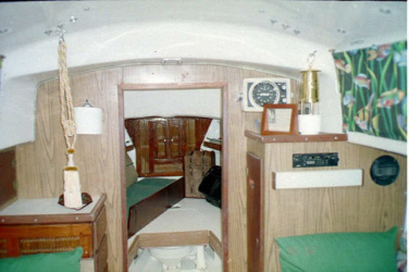
Although a number of Ariels have been upgraded to a greater degree, the primary goal in the restoration of "Augustine," was to create a safe pleasant interior primarily for use in single handing, without incurring the expense of removing and replacing the original Formica, while retaining the original design features to the maximum extent practicable. Toward that end, the primary chandleries utilized for the upgrade were West Marine, and those other marine stores, Ross Dress For Less, and Cost Plus.
All wood trim was removed from the interior, sanded, refinished and reinstalled. The painted surfaces were stripped with hand and power stripping tools. The interior surfaces were primed and then painted with white Interlux Exterior Marine Enamel. The teak plywood floor was sanded and oiled with Starbright Teak Oil.
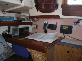
The ice box was removed by the previous owner and replaced with a nicely designed custom chart table. The original icebox lid opening in the bridge deck is sealed with a Lexan panel that admits light to the chart table. See plans for this table in the Pearson Ariel Owner's Manual.
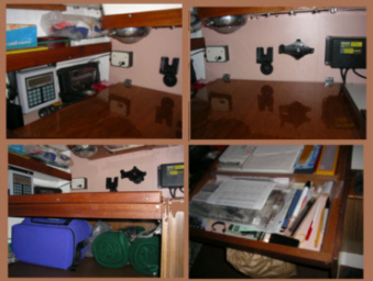

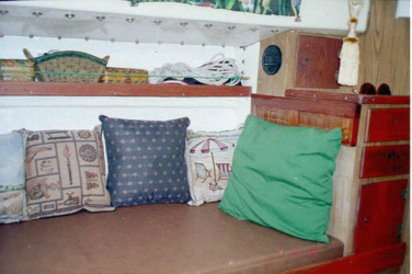
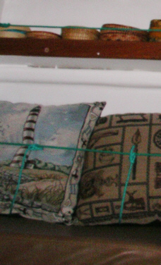
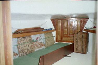
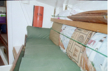
The main salon was updated in 2002 with new leather grained vinyl cushions, and pillows. The boxes on the longitudinal shelves are held in place by the original teak fiddles and new green nylon line. Similar lines are used to restrain the back cushions. Four lines (one for each cushion) are secured to the horizontal cushion restraint line, pulled down over the cushions, and pulled beheath the settee cushions. The cushion restraint lines are attached with simple bronze clips that can can be removed when not in use.With the restraining lines in place, the cushions remain in place at forty (45) degrees of heel. Without the restraining lines, the cushions remain in place until twenty (20) degrees of heel. The boxes on the longitudinal shelves contain shackles, blocks, self steering gear, safety harnesses, short lengths of line, gaskets, and miscellaneous hardware.
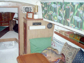
Please note that this first set of photos were taken prior to the structural retrofit completed in 2004, which changed the appearance of the main bulkhead. The retrofit project is chronicled on the Structural Retrofit Page.
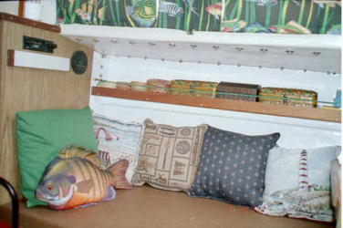
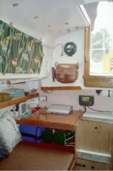
Tropical fish curtains, green cushions and fish pillow are courtesy of pervious owner. Further improvements are planned for aft-facing wood grained Formica bulkheads in main salon.

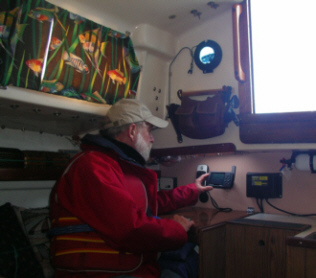
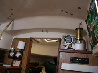
Note that the brass oil lamp rests in a standard plastic cup holder. The cup holder is secured to the top of the wet locker by a Velcro patch. It can bee easily removed. The lamp will work with or without the plastic restraining cup in place, however at night at sea in windy conditions I use the restraining cup.
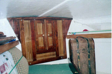
The hanging tassel on the port side of the cabin above the dresser is a simple curtain sash. A secure knot was tied in the sash. This knot serves as a hand hold. Combined with the two teak handles on either side of the companionway hatch, and the cabinets, this knotted sash makes it possible to have a secure handhold at many locations in the main salon.
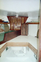
The V Berth was converted to serve as a single third berth with lee boards. The center panel of the lee board assembly removes easily to permit access to the head. The two cushions that make up the V berth mattress are four inches thick. They double as cockpit cushions for relaxing in the cockpit. They were designed as patio chair pads with an integral seat pad and back rest. They are quite comfortable in the cockpit for reclining against the back of the cabin.
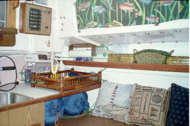
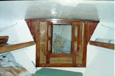
The anchor locker was separated from the main salon by a wood and bamboo panel with double access doors. The entire panel can be easily removed to permit full body access to the anchor locker for maintenance by loosening four wing nuts and pulling the panel off the bulkhead.
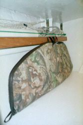
A padded bow bag designed for hunting bows was used to store the Garhauer lifting davit used to lift the outboard motor. It is attached by its carrying handles to two cup hooks mounted to the back side of the shelf fiddles.
The teak weather boards shown in several of the above photographs are not stored ther anymore. At forty (40) degrees of heel in a large swell one night, they flew across the cabin. The weather boards are now stored beneath the starboard settee.
A structural retrofit was completed in 2004 to the mast support system. The mast was removed, stripped of paint and waxed. All mast wiring and electrical fixtures were replaced. Spreaders were removed, inspected and refitted, a new antenna and coaxial cable and a new wind vane were installed. All standing rigging was replaced including wire, turnbuckles, and chainplates. The deck section beneath the mast was reinforced top and bottom and recored with a water impervious core. The strong back was reinforced. New gelocat was applied above and below to blend into the original surfaces. A separate Structural Retrofit Page cchronicles these improvements.
The two photos below demonstrate the change in interior appearance at the main bulkhead
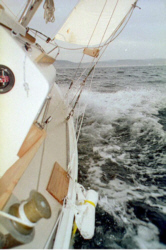
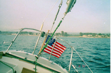
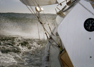
Note that in the last photo above, the boarding ladder on the starboard side washed overboard when Augustine was heeled to 40 degrees a moment before this pohotograph was taken. The ladder is attached to the eye bolts at the forward and aft edges of the boarding step and remains in its stowed configuration, and thus no harm is done. The installaton of the starboard jackline, which runs across the stowed ladder prevents this from happening. One of the photographs below shows the jackline in place.
No photos of other Ariels are currently posted on this site. See our Pearson Links for Ariel photos on other pages, or view other Ariels by using the links below:
To view photos of Ariels on other web sites use these links:
Illustrations, Pearson Ariel drawings, several of which are originals by Carl Alberg, and drawings of the Commander are included in the Pearson Ariel Owners Manual. Please contact the Pearson Ariel Association at:http://www.pearsonariel.org/ for a copy of the manual. I own one, and I think that you will be happy that you do too, if you own an Ariel and purchase one of these helpful manuals.
Back To The Augustine Table of Contents
Return to Solo Publications Web Index
This page was created by myrmade@solopublications.com