
Photos of "Structural Retrofit"
"Augustine" Photo Page
"Augustine" Home Page
"This Sailing Page"
Augustine Sheet-to-Tiller Self-Steering Page
Augustine Oar Page
e-mail to: myrmade@solopublications.com
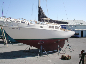
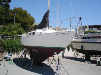
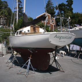
The focal point of this page is the restoration of and modifications to "Augustine," Pearson Ariel hull #330
The purpose of this website is to provide information on the Pearson Ariel, and to provide a portal for access to on-line information on the Pearson Ariel. Links are provided to other Pearson web sites.
This site has no affiliation with any manufacturer of sailboats.
The restoration of Pearson Ariel Hull #330 began in September 2001, with:
These improvements and others completed between 2001 and the spring of 2004 are documented on our Ariel Photo Page.
In addition to the above improvements, a complete structural retrofit was completed in 2004 after an accident caused damage to the mast base and support structure.
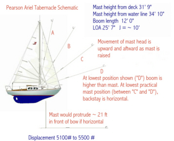
As to the accident itself, the drawing below displays a schematic that I prepared of the tabernacle operation based on an artist's rendering of a Pearson Ariel under sail. Please note that the sails would not be raised during a tabernacle operation.
As can be seen in the drawing below, when the mast is raised, it moves both upward and aftwards. If a mast is raised too quickly from somewhere between C and D to somewhere between A and B or to somewhere between B and C, it is possible to strike a bridge even though the masthead is initially extended beyond the bridge.
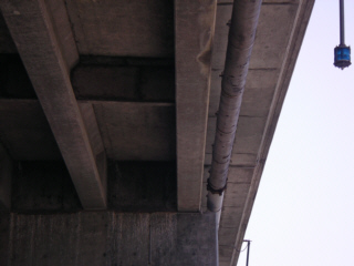
The Murray Street and railroad bridges span the Santa Cruz harbor at a low elevation. They stand side by side. It is necessary for all medium to large size sailboats to lower their masts to pass beneath these bridges. The Murray Street Bridge is just south of the Railroad Bridge.
The mast on my Ariel is thirty-one feet in height. The mast base is approximately three feet above the waterline, and the mast base is approximately ten feet aft of the bow.
This means that the mast, if extended to a horizontal position, would extend approximately 21 feet in front of the bow.
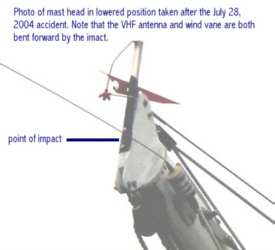
The accident occured when the mast was brought up and back more rapidly than was planned, thereby damaging the components on the masthead and forcing the mast down and back cracking the deck and the cabin liner. The mast base support bolts were foced down and back and were bent by the force of the collision.
The post-accident retrofit consisted of both accident repair and other modifications. These additional modificattions were necerrary becaause:
Although they were not directly necessitated by the accident, they were appropriate to the effort because the rig had been stressed in the accident, or
They were appropriate to restore the vessel while the vessel was not in service.
The retrofit consisted of:
![]() Back To The Top
Photos of the Structural Retrofit Project
Back To The Top
Photos of the Structural Retrofit Project
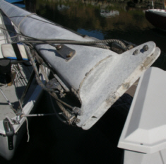
Rudder Restoration, Through Hulls and Hull Work
Thanks to a plastic hammer, and a can of anti-corrosion compound, I was able to remove the the tiller head fitting. I discovered that an aluminum Pepsi can had been used as a shim to prevent the "jaws" on the tiller head fitting from closing before the tiller head fitting was clamped tightly to the bronze shaft.
So, we have a chromed-bronze tiller head fitting secured with stainless steel bolts and an aluminum shim to a bronze rudder shaft.
The rudder shaft bearing and its O rings looked exactly like the ones in the technical drawing in the appendix of the Ariel Association Maintenance Manual. It fits in the top of the rudder tube snuggly over the bronze shaft inside the rudder tube. The outside diameter of the top rim (flange) of the "bearing" is the same as that of the outside diameter of the rudder tube.The Delrin rudder shaft bearing (white plastic bushing) and its O rings look as if they are nearly new.
The shaft "bearing" has been on the boat for some time apparently, but there is very little if any wear.
It seems that one could use a plastic shim instead of the Pepsi can, or even better, file a small amount of bronze from the inside of the jaws of the tiller head fitting to permit the fitting to formly grasp the shaft without fully closing its jaws. However, still considering a better solution, I noted that the Pespi Can had lost some of its original thickness, sine it is a less noble metal then the bronze shaft and tiller head fitting. I decided to manufacture a new Aluminum fitting to replace it pending a permanent solution.Since I prefer to drink root beer over Pespi, I made a new shim from a Mug Rootbeer can.
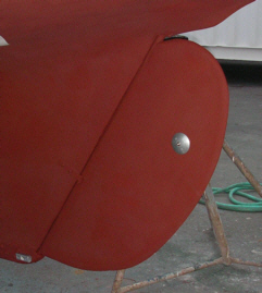
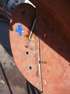
Removal of the rudder head fitting and the bronze strap that holds the rudder shaft in place below water, I was able to lift the rudder from the shoe so that I could inspect the shaft, and repair the rudder.The rudder and shaft were stripped of it's bottom paint and the rudder was repaired as necessary.
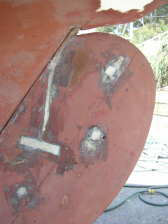
The excessive play in the rudder was due to loosening of the bolts that hold the rudder boards onto the shaft. The heads of these four bolts are ground to the radius of the rudder shaft. The nuts securing the bolts are accessible through square inspection holes in the rudder boards. By grinding off the bottom paint these holes can be easily located.
On Augustine's rudder, the square inspection holes had been previously filled with 3M 5200 or a similar substance, and then capped with resin. Opening the holes was not exceedingly difficult. All four holes were opened and the bolts were tightened. Once the rudder was repaiired, these holes were filled with polysulfide caulk and capped with a thin layer of West Systems epoxy.
All through hulls fittings were removed and replaced with new. New Groco one and one half inch through hull fittings were used on the cockpit drain lines.
Groco sea cocks have NPS threads on the bottom (seaward) end and NPT threads on top end. They currently manufacture their thru-hull fittings with NPS threads with the exception of the top section of the threads, which are NPT threads to accommodate in-line valves for above water applications. This "Combination Thread" works well in the NPS threaded sea cocks manufactured by Groco.
All plumbing was replaced and the scuppers in the cockpit floor were reinforced. Screw holes from the scupper cover plates that penetrated the laminate were patched.
 In 2010, I decided that it was time to try it again the right way.
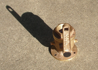
The capable and very professional people at Aquarius Marine in Santa Cruz removed my two Groco sea cocks and two inline ball valves along with all four thru hull fittings. The two seacocks along with three additional sea cocks were installed IAW American Yachting and Boating Association (AYBA) standards.
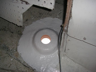
Pre-drilled resin saturated plywood blocks were glassed onto the interior of the hull, and covered with additional layers of glass, and finally a layer of gelcoat.
The seacocks were mounted to the resulting raised pads with bronze screws.
I decided to have a fifth thru hull installed for the sink to eliminate the "T" in the port cockpit drain. I reasoned that this would prevent an accidental flooding of the cabin due to a blockage in the cockpit drain below the “T”.
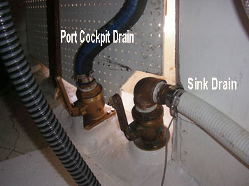
I now keep the sink drain closed unless I intend to use the sink for something other than a storage bin for items that I can reach from the cockpit. Shown in the photos abvove and below are:
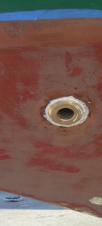
1. The port-side cockpit drain before mounting of the seacock
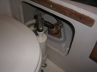
2. The completed raw water line for the head.
3. The completed port-side cockpit drain
Although it is possible for a long armed sailor to reach the handle of the sink drain seacock from the door of the cabinet beneath the sink, the handles on the cockpit and sink drains are best accessed by removing the companionway step assembly where all the handles of all three seacocks can easily be reached.
A bulge on thehull on the starboard bow below water told me that I had a blister. When we parked the boat with the starboard side to the south, a small bleeb of green resin-smelling material appeared. So I decided to open what turned out to be a fair sized blister.
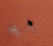
Upon grinding with a disk sander, I discovered cracks radiating outward from the central bleeb. I chased these to their bitter ends and as I did, brown water poured out for a time. I removed most of the water by applying pressure to the damaged laminate with a screw driver and continued to grind away with my sander until I removed all fractured glass. This took me down a layer or so.
There had been some delamination, Oddly, this delamination continued into an area where the glass and space in between was completely dry. It appears that the first and second layers of glass were either laid-up at different times or were not sufficiently wetted-out. One wonders whether the Pearson folks laid up the gelcoat and first layer of glass one day and waited to day #two to lay up the remainder of the hull. This was for a time the practice of many boat builders, or so Don Casey writes, and this practice would create a weaker bond between layer # one and # two and facilitate both delamination and more rapid lateral transporation of osmotic and/or other water.
Another possibility is that this long-ignored blister just ate up the resin between these two layers, but the fact remains that the space beyond the bulge of the blister (as delinated by the cracked and bulging area) was absolutely dry. I more or less followed Don Casey's advice in his fine and easy to read book on fiberglass repair.
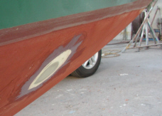
This photo is of the completed repair. I needed to do a light finish sanding and add bottom paint, but this third photo is taken after grinding away all weakened and wet surfaces until I had a very solid and very dry undamaged area, thoroughly washing the area, then drying the area both by air drying, application of hot air (hair dryer), and several applications of acetone, and then air drying once again. I wiped the area down once again with acetone, and then applied un-thickened epoxy to the original laminate ("delaminate"), and laminated five new layers of #10 weight fiberglass cloth with West Systems epoxy.
I then faired out the remaining space with colodial silica-thickened West Systems epoxy in two layers to obtain a fair surface corresponding to the curvature of the hull in this location. I spent an afternoon and a few hours on a second day on this project, allowing the epoxy to kick and cool between every two layers of glass, and between each layer of thickened epoxy. I sanded between the final two layers of thickend epoxy to better fair the area in preparation for the final coat of thickened epoxy.
I also repaired two other blisters on the hull in the same manner. These were the only blisters evident on the hull.
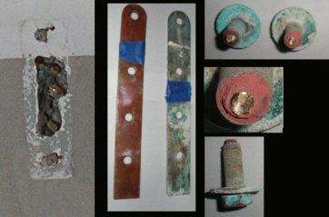
The original bronze chain plates were removed. Corrosion to the plates and bolts was evident.
The original chainplate slots were cut directly through the deck and cabin ceiling laminates and through the balsa wood core in between. Water intrusion resulted in local erosion of the deck core.
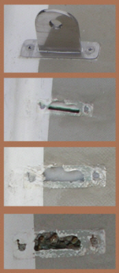
In the photo to the right, a single chain plate slot is shown in various stages of repair. The delaminated deck core was removed in the area of the slot. The bottom of the slot was capped with epoxy. Epoxy was then pumped into the deck core until it squeezed from the slot and the screw holes for the chain plate covers. A new slot was cut using a drill and a saber saw.
Below deck, the areas of the bulkheads adjacent to the chain plates were stripped of paint with a drill fiitted with nylon brush head and then sanded. Voids and the spaces between the plywood bulkheads and deck were filled with fiberglass cloth and epoxy. Glass fabric and epoxy were added to reinforce the bulkhead. The boltholes were reopened using a drill and file.
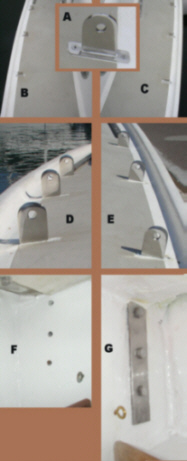
New chainplates and covers were manufactured from 316 stainless steel.
The new chain plates were dry fitted in their new epoxy-lined slots and then installed with polyurethane bedding compound. Finally the new chainplate covers were bedded and screwed into place.
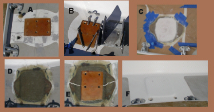
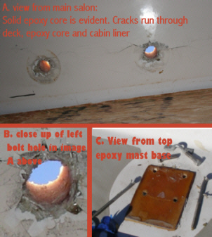
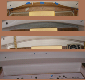
The composite photo to the left shows the new installed 3/16 inch thick 1 1/2 inch wide 316 stainless steel chain plates with their new covers installed. photos A and B show the chainplate slots before the instrallation of the plates. Photo D shows the three starboard chainplates without the chainplate covers in place, and E shows three of the portside chain plates without the chainplate covers in place. Photo F shows the main salon side of the bulkhead after it was reinforced and repainted, but before installation of the aft lower chain plate. Photo G show the port side upper shroud chain plate after installation.
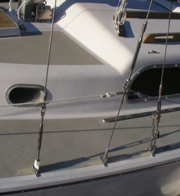
The photo to the right shows a section of the new rig installed. The Norseman fittings and tangs were inspected and reused. All swaged fittings, turnbuckles, and all wire were replaced with new.
Deck and Mast Support Retrofit
Once the mast was off the boat, the deck cracks were evaluated. A previous retrofit (an epoxy plug with horizontal dimensions equal to the tabernacle mast plate) was removed. This plug had been installed by a previous owner to replace the deck and core section beneath the mast.
The photo to the left is a composite of photos taken during the repair process:
Photo A. Shows the original epoxy plug
Photo B. Shows the stainless steel mast plate with damaged bolts beside the old epoxy core insert
Photo C. Shows the new Q Cell core after it was poured, but before sanding
Photo D. Shows the area after the top section of the laminate was completed
Photo E. The image in photo A was superimposed on the image in photo D to create photo E. Cracks caused by the accident are highlighted in white. These cracks were removed by grinding prior to building the new deck section.
Photo F. A new slightly raised mast base is shown in photo F. after the application of two coats of gelcoat and sanding. The color of the new gelcoat matches perfectly the forty-year-old surrounding gelcoat.
The epoxy plug was not an overlay, but completely filled the deck core. This is not a standard feature, but was added by a previous owner who added the tabernacle deck plate. This was his solution to delamimation beneath the original mast step plate I suppose. It worked well enough until the mast struck the bridge transferring the full force of the impact on this area forcing the epoxy plug downward and cracking the cabin liner aft of the main bulkhead. This epoxy section appeared to be a solid epoxy pour.
All deck cracks in the deck outboard of the epoxy plug were followed both horizontally and vertically with a grinder until undamaged top deck sections and undamaged balsa core was reached. This work was done by a professional.
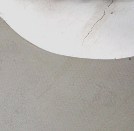
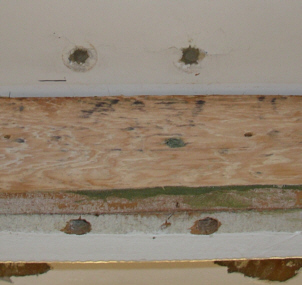
The photo to the right shows the principal crack in the cabin top deck adjacent to the mast. This area of the deck absorbed the impact of the collision. Note that the crack continues into the non-skid area. There is evident compression damage to the deck also. This compression damage does not show in this photo, but you can see from the cabin liner photo that compression impacted the cabin liner as well. The main deck crack in the photo is strattled by brown looking fractures.
This area of the deck was cut away from the top. A new core and top fiberglass laminate deck was built in this area. The cabin liner was repaired to make it an integral part of the deck laminate. The strongback was reinforced to make it an integral component of the deck structure by wrapping it with multiple layers of unidirectional cloth and triaxial cloth, extended foward and aft to layer them over the interior laminate foreward of the bulkhead and the cabin liner aft.
I thought that the door through the main bulkhead looked a bit saggy also until I removed the Formica above the door and the doorframe. Cutting the plywood above the door in a straight line didn't seem to be a priority for the builders, but there doesn't seem to be a bit of compression above the door. The strongback and plywood appear to be in like new condition.
When my mast accident shoved the mast down into the deck, it did so at an angle since the mast was partially lowered when it hit, and that shoved the tabernacle deck plate down and back, compressed the deck lamination, and forced a couple of bolts to push down and crack the cabin liner aft of the main bulkhead in the main salon, but there still is no observable deformation of the main bulkhead or strongback over 39 years of sailing.
In the photo of the cabin liner damage in the "An Odd Discovery" section below, you can see the dip in the white cabin liner, but the liner rises to it's original height just aft of the plywood bulkhead surface .
The top of the deck was depressed in the vicinity of the mast step by the accident. The mast base was damaged, and the mast step plate was lifted from the deck in the front and driven down into the deck in the back. Two bolts attaching the tabernacle mast step were driven through the cabin liner behind the main bulkhead. The solution to these problems was grinding away the deck laminate and core chasing all cracks in the deck section (top), and then replacing all of the damaged glass and core with solid fiberglass and Q cell core, and then fairing it all out to match the rest of the cabin top. This was done from the top side. The photo on the left shows the deck follwong the repair but befoe the mast was re-stepped.
The bottom side of the deck was also be delt with by chasing cracks with a grinder, and replacing and reinforcing all damaged glass, then tying the liner, and deck together to the reinforced strongback.
There was nothing to shim from below, because the beam as far as I can tell is “as built” with absolutely no sagging and no separation of depression caused by the impact. In other words, the strongback ably withstood the force of 6000 + lbs (boat plus three crewmembers and gear) coming to a sudden and complete stop, with said force directed at the six by ten inch tabernacle mast step directly above said beam. Now in all fairness, since the mast was lowered to shall we say 45 degrees, the force was diagonally aftwards, and so the rear portion of the mast base plate pressed into the deck at a location behind the strongback, and this is where those two bolts penetrate the cabin liner.
So despite the intuitive benefit of adding some stainless steel plates as others have done to PearsoN Ariels, the dis-benefit of drilling holes through what appears to be a perfectly functional strongback for any reason was a concern to me. That is why I liked the idea of a non-invasive approach such as beefing up the area with a laminated section of unidirectional or triaxial cloth to replace the Formica on the top of bulkhead on the main salon side of the main bulkhead and wrapping that around the strongback to form an equivalent reinforcement on the V berth side of the strongback.
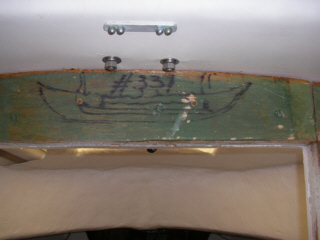
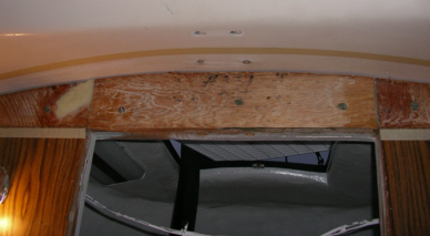
When I removed the doorframe in the main bulkhead and then lifted the Formica piece above the door. I discovered this very interesting drawing, which must have been made by a Pearson Employee in 1965 when my boat, Hull #330 was built. Oddly, the number above the drawing is #331.
The drawing proves the Viking influence on the design of the Ariel. Note that the vessel portrayed is a double ender with two masts. I cannot determine whether the drawing depicts a yawl, ketch, or schooner, because the rudder is not shown and the tops of both masts are truncated. There is some disagreement as to whether the horizontal lines on the hull of the vessel are intended to represent ocean waves, or whether they represent an ama.
For some reason the bulkhead intended for hull #331 was apparently installed in hull #330, or through some other process hull #331 became hull #330.
Note the crack running through the two larger bolts in the above photograph. The crack in the cabin liner is manifestation of damage to the only cabin liner resulting from the accident, but it reflects a loss in the integrity of the mast support structure. This was repaired as described in next section.
The photos in this section show the repairs completed below deck to the strongback, cabin liner, and bottom lamination forward of the main bulkhead.
Although like many other Ariel owners, I wanted my main bulkhead to be a strong as possible, it is worthy of note that after forty years of successive owners riding a Pearson Ariel hard and putting it away wet has caused no visible deformation of the strongback.
I removed the formica on the aft side of the strongback and sanded both sides of the strongback. I chased a few cracks and voids, but those led led me to workmanship and assembly issues that resulted during construction forty years ago when my boat was built, and were not due to damage caused by the accident.
I filled a few voids and strengthened a few areas. The bulkhead and strong back have served three owners well over the years. My somewhat destructive examination continued to show virtually no bulkhead damage from the accident, despite damage to the deck and cabin liner. Both professionals with whom I consulted did not feel that through bolting steel plates on either side of the strong back would be the best solution to strengthening the mast support system. In my boat there was no evidence of sagging in the strongback.
Once the teak door frame was removed, it was apparent that the horizontal beam above the door was level. One of the vertical frame members was actually vertical, but the other is not, so that the door opening is a lopsided trapezoid. Since the plywood opening is cut this way and there is no separation from the hull on either side or underneath, I must conclude that this “as built”, rather than “as failed”.
Although the Main-salon-side plywood bulkhead panel was not glassed to the cabin liner, I could see over this panel to what appears to be a glassed seam between the strong back and the deck. This seam was solid and there was no indication of sagging or separation. The area above the plywood on the Main Salon side of the bulkhead looked fresh and solid. I could drawn the same conclusion by looking at the seam between the strongback and the underside of the deck from the V Berth side. Removal of the paint from the strongback confirmend that conclusion.
The cracks that I chased and the voids that I discovered were probably left by the builders (the failure to wet out tabs holding key braces in place, voids in the fiberglass, (the use of AC plywood with significant internal voids, etc.). So I would have to say that my boat might have been both hastily built, but it was also overbuilt. Th Pearson Ariel is sort of like a Sherman tank built by the low bidder. This is one strong boat, albeit one built somewhat strangely in places.
Because it is conventional wisdom to strengthen the strongback, I contracted for reinforcement by a professional using unidirectional cloth and triaxial cloth. This was glassed onto the bulkhead and strongback in a sufficient number of layers to reinforce the strongback/bulkhead without drilling holes through it or installing steel reinforcement plates as have been used on some Ariels. This solution provided for the strongback to be glassed to the underside of the deck deck forward of the bulkhead and to the cabin liner aft of the bulkhead. When repairing the top deck, the new top laminate, bottom laminate, core, and cabin liner were reconstructed as an integral unit. Thus there is no longer void above the plywood section of the main bulkhead on the main salon side. This void was originally filled by that strange foamy wire-reinforced trim piece. That piece was glued into the void above the plywood. Those little wires are sharp and hard to remove.
The longer bolts in the mast base that had been inserted in the foreword two holes were seriously bend as a result of the accident. The bolt holes for these bolt were directly above the stongback. They penetrated the strongback directly above the doorframe. Their securing nuts were captive inside the beam. Inspection holes were provided in the bottom of the beam. Those holes were drilled completely through the teak door fame as well. The beam prevented the lower portion of the bolts from bending. In the accident, the bolts were pulled upward. The bends occurred at the very top of the bolts. The angle of the force of the impact pulled the longer forward bolts upward, and the shorter aft bolts downward as the mast step plate rotated aftwards into the deck. This effectively crushed the deck. This entire area was rebuilt and the forward bolt holes were relocated.
The cabin liner in the main salon was obviously distressed as can be seen in the images in this section. Less severe distress was evident in the forward salon, but some cracking in the lower laminate occurred..
The shorter bolts were driven down through the cabin liner causing the liner to crack and shatter.
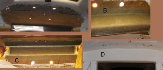
The photo to the left shows the V berth side of the strong back in various stages of repair.
In photo A, the cracks in the bottom laminate were removed by grinding, as was the paint on the central section of the strong back. The two holes in the deck are for mast wiring (Coaxial VHF cable on port and electrical wires for mast on starboard).
In photo B, multiple layers of vinyl ester resin and fabric were added to the damaged area and to the strong back to tie the deck section to and reinforce the strong back.
As can be seen in photo C the application of glass to both sides of the strong back and to the deck sections forward and aft of the strong back created a very strong integral structure to support the mast.
Photo D shows the area after the application of gelcoat. Screws protruding through deck are hinge screws for forward hatch....
The next composite photo shows the main salon repair in a single composite photo.
Photo A shows original plywood taped for application of product after minor repair of voids in plywood and sanding.
Photo B shows area after sanding of applied product. Strong back area (both sides and bottom) was reinforced with multiple layers of vinyl ester saturated fabric including unidirectional cloth and x mat.
Photos C and D show finished project after application of two layers of new gelcoat. The two holes aft of the strong back at the top of photo D are newly drilled holes for attachment of the mast base. The original holes were filled prior to application of glass and resin to the top and bottom deck sections. The new holes were drilled after the reinforced strongback was fully laminated and gelocat had been applied.
The photo to the left shows the finished project. The lamination extending from the cabin liner aft of the bulkhead around the strongback to the lower deck laminate in the V Berth area is continuous and seamless.The seam between the remaining Formica and the original gelcoat was sealed with 3M 5200 and topped with a bead of 5200.
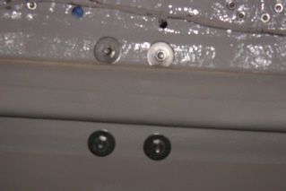
In the photo below, the new mast base bolts are shown with washers in place.
Mast Retrofit and New Standing Rigging
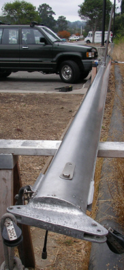
After nearly four months the process of accident assessment and repair was completed. The image to the right shows the mast immediately after it was un-stepped, but prior to any work being performed on it. The image on the left shows the mast after it was stripped, polished and waxed.
Although stripping the old paint from the mast was time comsuming, the removal of all mast wiring took even longer, since the wiring and coaxial cable had been bundled inside of foam tubing.
Open cell foam batting was wrapped around the tubing and taped in place at intervals for the length of the mast.
Becasue of the foam, the wiring assembly was extremely difficult to remove.The wiring assembly and foam must have been inserted some years before prior to installation of mast hardware after the mast was painted .
The spreaders had to be removed to facilitate removal of the wiring, since wiring had been run into the spreaders.
I contracted with professionals for the rigging and structural repair to the deck and strong back, but personally took care of the mast work, chain plates and reinforcement of the bulkheads, and gooseneck. In order to rebuild the deck and strengthen mast support structure following the accident the mast was unstepped, stripped of its paint, and rewired.
A new VHF radio, VHF antenna, coaxial cable, new steaming light, and new wind vane were installed. The spreaders were removed, inspected, and reinstalled.
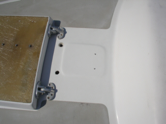
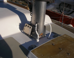
.The photo to the right shows the mast base after the mast had been installed near the end of the project. The mast was protected with three coast of marine polish with Teflon. Reapplication will be required about once every six to twelve months. With a tabernacle this will not be a major effort.
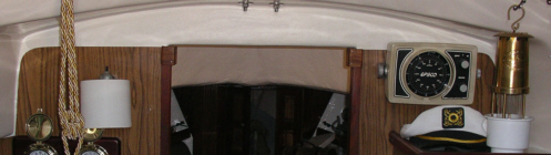
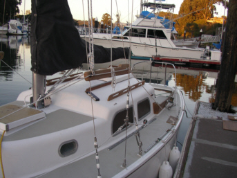
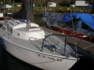
The photo to the left shows the new rig in place. The mainsail cover was later replaced with a new cover.
.......While we were at it, I repainted the interior of the boat.
Soft luggage is my solution to storage. The black bags are multi-pocket brief case style vinyl bags from Ross Dress For Less. They don’t scratch painted surfaces, and secure easily, and are easy to lug around the boat.
One of the two black bags holds my wrenches, vice grips, channel locks and pliers, and the other holds all of my other tools, with the exception of large tools and box wrench set, which store under main salon settees. The red bag holds 75 feet of towrope, a towing bridle, and a polypro throwing line with monkey's fist.
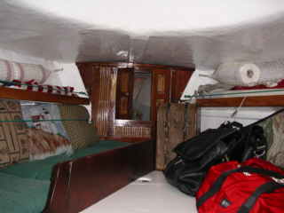
Behind the red bag is a padded bow bag (as in bow and arrow) that holds my Garhauer Lifting Davit. All soft bags secure to eyehooks mounted into the starboard shelf above the V berth.
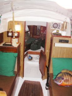
Pillows are Ross Dress For Less nautical theme pillows. The green cord holds the cushions securely in place. The pillows match those in the main salon.
The wood and bamboo partition between the V berth and anchor locker is secured by four bolts with wing nuts on the anchor locker side. The entire partition can be removed quickly to allow access to the anchor locker for more serious maintenance. The double doors allow reasonable access to work with the anchor, rode, and perform minor maintenance.
The lee board on the berth comes apart in secitions to allow easy access to the head below the V berth. The green cushions on the berth are two chair cushions that double as cockpit lounging cushions. They fit perfectly on the cockpit seats with the back of the cushions against the trunk cabin.
![]() Back To The Top
Back To The Top
Back To The Augustine Table of Contents
Return to Solo Publications Web Index
This page was created by myrmade@solopublications.com