Page 5 - Putting the Hull Together
by Dennis Lancaster
On this Page:
On Other Pages on This Site:
Strongback
The Hull
The Keel Assembly
Winter Slowdown (Winter of 2007-08)
Spring Start-up - Epoxy on the Hull
Summer Projects
Site Contents -
The Project -
The Plans -
The Materials -
Bulkheads -
Keel and Ballast -
Winter Projects -
Mast Fabrication -
Deck & Interior Assembly -
Rigging the Old Shoe -
Sailing My Old Shoe -
Boat Building Links
e-mail to: oldshoe_1@hotmail.com
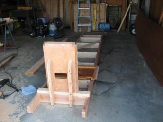
The Strongback was assembled in one day using construction grade lumber. Cost of Materials was around $60. I looked long and hard for the straightest sticks I could find for the 14ft runners. I used 2x6 for the runners and cross sections and 1x4 for vertical supports. The upright supports were ripped from 2x6 stock.
Squareness and alignment are very critical in building a Strongback. I spent several hours just insuring that those criteria were met. I placed my cross pieces at the bulkhead station lines such that the plywood faces of each bulkhead would be right on the station line.
The idea of the vertical supports is to lift the bulkheads relative to the plan baseline and at such a height as to be easy to work with while standing. This is not an easy task to calculate and I need to give credit to my good friend and shipwright Mike Keers who lives in Arizona, for providing me with accurate building plans for the Strongback and Bulkhead support layout.
For what its worth. I strongly recommend any who attempt this building project to consider using a Strongback. The plans do not call for it. Frankly, I just cannot see how a hull can be built without it and have it come out true.
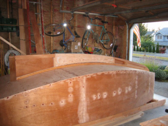
All frames have been mounted to the Strongback. This was a laborious task in aligning and truing each bulkhead. I truly feel that the effort will be well worth it. I have installed all cockpit framing supports dry and will be soon gluing and screwing them in permanently.
A couple of issues are worthy of note. The outside cockpit seat stringer is only shown to run between bulkheads B and D. This is perfectly fine, but I am considering extending this stringer all the way to the stern bulkhead. My reasons are two fold. I feel it will give natural support to the hull sides and also provide additional support to the stern area.
One other builder has experienced a cracking at the port upper stern corner over time, due to stresses placed on the stern from the mizzen. His recommendation was to add an upper gusset to that corner for additional support. I will be doing so, but feel I want the added support of that stringer. This is not a critical move, and if neither are done, the boat will serve well for many years, just as designed.
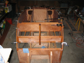
After installing all the internal cleats for seating, the chines were installed. Assembly instructions provided stated to install those chines "after" the sides are on. After much thought and discussion with my mentor, I decided to install those chines before the sides went on. This just made more logical sense as I know had something to clamp and screw to.
The building instructions also recommended "not" purchasing kiln dried fir for framing, as it tends to be brittle. When I placed my order for wood, there was no air-dried fir available, so I went with the kiln dry. This has worked just fine for all the framing pieces and cleats that do not take a bend. However, the chines, being ripped from that fir stock, took the bend, but then later cracked at two stress points. I was able to save one side, but had to replace the other side. The second installation was done with wet rag steaming and that worked out just fine. Just a word of caution, go for air dried fir if you can find it.
The sides are now mounted and screwed and glued in place. I must say that working alone; this was not an easy task.
I rigged a rope hoist from my rafters to aid in supporting the sides as I presented them to the hull framing. The sides were lofted per plans and cut with about a �" oversize margin.
Nothing is ever perfect in boat building and I had to work for hours to tease those panels into place, but they did pop in pretty darn close.
I will have to do some trimming, but that was expected. The screws were all silicon bronze square drive 1" and 1- �", counter sunk. All holes have been filled with epoxy filler.
I must say, she is starting to look like a boat!
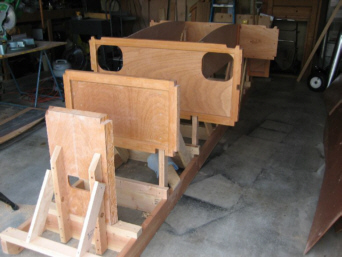
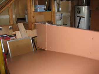
As you can see in the pictures, the hull panels are finally on the boat. They are laid on in three panels.Each seam takes a butt strip that is 4" wide by the width of the hull, minus the width of the chines.
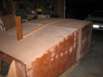
The strips were attached to the underside of each panel, using clamps and deck screws. I was surprised at just how quickly those panels went on. You can also see the first layer of the keelson attached to the hull, down the centerline.
I have to admit, that the keel has posed the most anxiety for me. I have spent many hours in the "moaning chair" trying to sort out how I was going to assemble the keel, insert the lead ballast and then finally hoist it onto the boat. Here is what I have done so far:
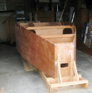
I decided to do a "mock-up" of the keel right on the hull, using the wood plug I used to cast the lead ballast. I first presented one side of the keel panel to the hull and made any fairing adjustments so that the panel would fit the shape of the hull. I then attached the panel to the sternpost and keelson.
The framing came next, per plan. I added cleats to either side of the ballast to form a framed chamber or slot in which to insert the lead ballast. It made sense to me to do it that way, although the plans do not show that. I then added the front side panel, cut to fit and added the framing there as well. You can see how this came out in the pictures.
My next task was to drill the drain holes that will be used for the water ballast compartments of the keel. I then fit and mounted the other side panel to complete the assembly. All screw holes have been pre-drilled and counter sunk. The assembled keel was lifted from the hull.
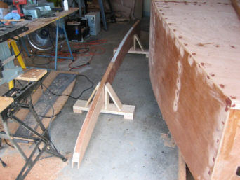
I built two support frames that will hold the keel in the vertical and off the floor so that the delicate side panels are not crushed. I figure the completed keel with lead ballast will weigh in at around 250lbs. Having the keel in the vertical position will make lifting a lot easier.
Here is my plan for the keel assembly and attachment to the hull:
1. After all the keel pieces have been coated with penetrating epoxy, I will glue in the frames on one side. It will be important to keep the slot for the keelson clear of any residual epoxy (squeeze-out).
2. After curing, I will lay the first side on the concrete garage floor on top of plastic. I will then apply liberal amounts of epoxy to the slot where the ballast will rest. With help, I will lift the lead ballast into the slot. After that kicks, I will epoxy in the other side panel on top, keeping that keelson slot clear. I will drive in numerous silicon bronze 1.5" ring nails into the lead ballast area.
3. After cure, the keel will be flipped and ring nails driven into the other side. The keel will be lifted and set on its support frames in the vertical (as the picture shows of the mock-up). Steel �" rods will be inserted through the drain holes fore and aft of the ballast to act as lifting points.
4. I purchased a � ton chain fall and attached it to a 4x4"x6' beam that I placed across 3 of my rafters. Using the lifting straps and help from friends, the keel will be hoisted up and set down onto the keelson and epoxy and screwed in place.
Well, that is the plan, stayed tuned for what really happened later.
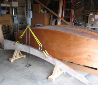
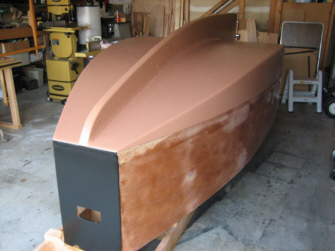
On September 8, 2007, I reached a milestone. The keel is finally on the boat.
 A solid two weeks was spent assembling the keel on the garage floor, setting the lead into the keel frame and then fairing and glassing each side. I think that the keel has been the most taxing phase of the building project to date.
The lift went just as planned, with a few changes. As you can see in the attached pictures, I was able to slide the boat over to side of the garage and move the keel, in its support stands over so that it was directly under my chain hoist. I made two �" steel pins that were driven into and through the lower drain holes on either side of the lead ballast. These made for perfect pick points for my slings.
The � ton chain hoist may have been over kill, but it sure was comforting as it effortlessly hoisted the 250lb keel assembly into the air. I then slide the boat back under the keel and lowered the keel into position over the keelson (which had been coated generously with epoxy). A few knocks with a large hammer, and she was in.
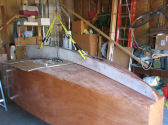
I have to admit that a big load is now off my mind. As always, it was not as bad as I had imagined it to be and I can easily see why a full keel boat is somewhat daunting to someone considering this design to build. Frankly, I am puzzled as to why some builders would attach the keel with the boat right side up or even on its side. But to each his own method I guess. I think this is the way to go in my humble opinion.
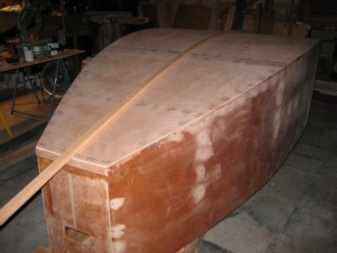
The next task was to fair the bottom edge of the keel and add the fillets to either side of the keel to hull seam and glassing same.
As of September 27, 2007, the keel was firmly attached to the hull.
The chines were taped and the keel to hull seam was fully filleted.
-
-
Winter Slow Down (Winter of 2007-08)
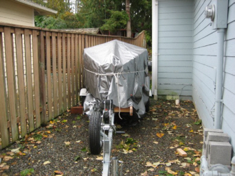
As of October 19, 2007. Winter was officially upon us in the great North West. Due to consistent low temperatures and the need to bring my car inside for the dark months, I moved the hull, still on its strong back, up onto the trailer and out into my side yard with full cover (see pic). I had to remove the bunks from the trailer so that the strong back would slide onto the trailer frame. I hoisted the entire hull and strong back assembly using my chain hoist, which effortlessly lifted an estimated 500lbs 17inches up into the air. I then backed my trailer underneath and by using the trailer winch and some manpower, slid the unit onto the trailer and then lowered her down. I used my pickup to back the trailer into the side yard, then covered the hull with a good tarp and strapped her down for the winter rains, wind and snow ahead.
I did manage to fiberglass the entire bottom and get it filled and faired before stopping.
My winter plans are to complete the sprit booms and router the edges of the rub and cap rail material. I am also planning a knee replacement surgery during the month of December, so that will slow me down some. I am already anxious for spring to come and once again seeing the boat coming to life in my garage.
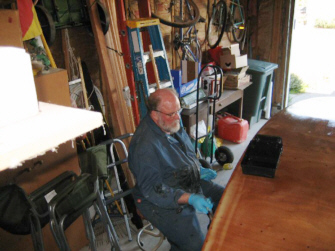
As of February 10, 2008. Low temps. Have halted any varnish or epoxy work. After successful knee surgery, I have busied myself with tool maintenance (sharpening planes, and jointer knives). The purchase of new equipment: Dust Collector (Grizzly), Router and router table (Porter Cable), Drill Press (Grizzly), mobile Jointer stand (Grizzly) and more clamps (Bessy and Jorgenson). I got out the motor mount and am awaiting warmer temps to laminate and shape. Before the cold really set in, I was able to get out both spars and apply several coats of varnish. Next month should see the return of the hull to my garage and as the temperatures warm, epoxy and varnish work will resume. I am greatly anticipating this up-coming phase of the build, as hull turning and project completion are slated. Stay tuned.
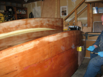
As of May 2008, temps have warmed enough for me to start laying on epoxy to the hull. The first coat has been applied; there will be 3 coats before bottom paint goes on (1part poly, 3 coats).
Winter was not a complete waste, as I applied varnish to the mizzen, two booms and the tiller. I got out the motor mount and have applied two coats of epoxy to that.
I splurged on shop tools and purchased a new Powermatic cabinet saw, 14" band saw and Jointer. It is a pleasure to finally have good quality tools to work with.
My left knee replacement was a success and I am just about healed up.
-
-
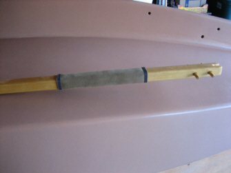
As of June 2008, I have applied varnish to the main mast, mizzenmast, main boom and mizzen boom. The mizzenmast is completed, the main needs one more coat and the mizzen boom is done with varnish.
I have applied a leather anti-chafe to one section of the mizzen boom, where it will come in contact with the mizzenmast. I purchased what is called "oar leather" from Wooden Boat Store. I used the tacking method and then whipped the ends with waxed string. I'm very pleased with the results and plan to do the same with the main boom.
As of June 2008, I have installed the bottom rudder pin, painted the rudder with bottom paint (I have changed my color scheme on the boat and am using a oil based enamel from Benjamin Moore called "Copper Mountain" to try to come as close to a copper look for my bottom paint. The topsides will be black).
I have now mounted the rudder to the keel using a stainless steel shoe. I will complete the upper bearing after the hull is turned.
.
.
.
.
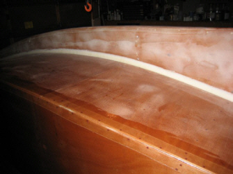
As of June 2008, I have finished coating the bottom with epoxy and have applied two coats of Benjamin Moore oil based enamel called "Copper Mountain".
I have decided to go back to my original desire to have a black-hulled boat and will be painting the hull sides black after hull turning. I went ahead and painted the bow bulkhead black to see how it looks. I'm very pleased with the look.
Next is to build a rolling cradle to get ready for the hull turning event coming soon. Please see my Deck & Interior Assembly page for photos and a description of that effort.
This page was created by oldshoe_1@hotmail.com
Return to This Sailing Page -Home
Return to Solo Publications Web Index
May 29, 2008